The Novanex R12000 is a BBD reverb unit, not known to be especially good.
This unit uses 4 of the very rare NE503 BBD chip produced by Phillips.
The datasheet of the NE503 is not easy to find and the service manual of the R12000 is in Dutch.
If one of the NE503 dies, you won’t be able to find a properly working replacement. In that case, just bypass the faulty one with a short wire connected between pins 3 and 6. The reverb duration will be limited.
So here is the translation of the unit adjustment procedure:
Buttons:
Delay = 10
Volume = 10
Tone = 10
Repeat = 0
V – in = 30 mV 500 Hz
Adjust trimmer 7 so that the notches are aligned. Last NE 503 should be flat. (i.e., not to be skipped over)
V – in = 30 mV 500 Hz. Adjust wheel trimmer 1 so that the VU meter = 0 dB.
Turn the noise trimmer, scope on output, and adjust V – in = 50 mV. Use trimmer 2 to ensure the sine wave remains undistorted. (Check symmetry here.)
Scope at measurement point, V – in = 30 mV. Adjust trimmer 3 so that the signal remains straight up to 4500 Hz.
Scope at output. Adjust trimmers 4 and 5 to keep the signal straight up to 5000 Hz.
Fine-tune trimmers 4 and 5 by ear.
Adjust the noise trimmer by ear.
Adjust repeat by ear.
Note:
The delay setting may vary for auditory tuning.
For steps 6–7–8, first adjust the delay so that it matches the reference model from the test room.
This article details my hypothesis on why this actually made the trick.
Tuning the DIP switches
The H8 CPU boots with CS0 enabled by default, thus the program is accessed on whatever memory is connected to the main bus and enabled by CS0. According to the schematics, we can see that the switches A and C should be used to boot on the Flash memory (A) or the PCMCIA BUS (C). Default switch position is A, in order to boot on the Flash memory. In our case, we suspect the flash to be corrupted and we want to boot on the PCMCIA card instead. Thus we set A to OFF and C to ON.
When the H8 program needs to access the PCMCIA card it uses the PCMCIA_MEM_CS which can be routed to PCMCIA BUS (by setting switch B) or FLASH CS (by setting switch D). Clearly, the default position is switch B: we want to route PCMCIA accesses to the PCMCIA BUS. When flashing the main Flash, we’re in a different setup: the roles of the PCMCIA card and the internal flash memory are inverted (we boot on pcmcia and we want to write the flash). Thus, we set it to B disabled and D enabled.
The switches E and F are funny. By default we set them to OFF, which sets the H8 memory access to 16bits (MD0, MD1 are set to gnd and MD2 is set to 5V. This sets the H8 CPU to « Mode 4 »). Now we want to boot on the PCMCIA which is an 8 bits memory so we set these switches to ON ON (MD0, MD1 are set to 5V and MD2 is set to GND. This sets the H8 CPU to « Mode 3 »).
Switch G is used to enable the external RAM memory. This is the default setting and we still want external RAM.
Switch H is used to enable the flash chip. Since we plan to write on the flash memory, we will need it.
Switch
Position
Why?
A
OFF
We don’t want to boot on the flash
B
OFF
Roles of PCMCIA and Flash are inverted so don’t root pcmcia accesss to pcmcia
C
ON
We want to boot on the PCMCIA, so boot_cs goes to pcmcia
D
ON
Roles of PCMCIA and Flash are inverted so pcmcia accesses go to flash
E
ON
Set MD0 and MD1 to 5V for Mode 3 (8 bits).
F
ON
Set MD2 to GND for Mode 3 (8 bits).
G
ON
Keep the external RAM in use.
H
ON
Keep the flash memory in use.
Mv6b20.ins
Initially the Mv6bv20.ins was sent to me by the TC support (Musictribe). They told be to put it on a floppy disk and boot on it. Since my M6000 was crashed it never tried to read on the floppy.
I tried to reverse the Mv6bv20.ins but a few things were strange to me:
This firmware was labelled « boot », but if it’s a bootloader what mecanism is supposed to « read on the floppy and write on the flash? »
Musictribe told me to write it on floppy and « boot » on it, so there’s must be a bootloader somewhere
The assembly code of this firmware, shows that a large portion of the code seems to be duplicated at address 0x1001C. Why?
It’s pretty hard to understand if the memory adressing is 8Bits or 16bits, depending on where you look. Are we in Mode 3 or Mode 4?
I was wondering if the first main program at addres 0x000000 could not be the bootloader and the second one at address 0x1001C the actual main program. But thus, why is not the adress 0x1001C not fitting into a specific block of the 28F800 flash chip?
The answer it that the Mv6bv20.ins binary is not a firmware, it’s a flash tool. When run, this program will write the data at 0x1001C address to the flash chip.
When reading from the PCMCIA SRAM, we’re in 8bits mode adressing, that why our first « main » program (the flash tool) uses 8bits address and the second one (the actual firmware) uses 16bits mode adressing.
Clearly, writing the file (M6bv20.ins) on a floppy disk and inserting it on a faulty M6000 was pointless.
So, after many attempts and experiments I was able to boot my M6000 and bring it back to life!
Soluce:
Use this procedure if your unit crashes during boot (front panel never turns green + floppy disk drive is never accessed).
For the impatients, here is the soluce (see below for the how and why):
Write the M6bv20.ins on a DOS Formatted (FAT32) floppy disk and rename the file to « dumpfile.bin »
Find a 1MB or 2MB SRAM Flash PCMCIA Type 1 (the SRAM characteristic is essential, a simple PCMCIA flash adapter won’t do the trick)
Find a working M6000 unit (ask a nearby studio, this is litellary a 20 seconds manipulation)
Insert the floppy disk and the PCMCIA card on the working unit (unit is ON)
Go into « Frame > System > Main > Card » and press « Dump binary file to card ». The floppy disk is read and dumpfile.bin is written on the pcmcia flash card.
Now eject the floppy disk and extract the PCMCIA card.
Turn your faulty M6000 off
Set the internal DIP switches to OFF OFF ON ON ON ON ON ON
Insert the PCMCIA card and turn the unit ON
The Front panel led will turn orange then green after a few seconds (around 10s)
Turn the unit off and extract the PCMCIA card
Set the internal DIP switches to their default values: ON ON OFF OFF OFF OFF ON ON
Turn the unit ON
That’s it!
After this procedure, your unit should properly boot (front panel led is green) and access the floppy disk drive during boot. If you still have issues, think about reflashing the main software (write S6KAppl.M6K and m6kboot.ctl on a floppy and boot on it).
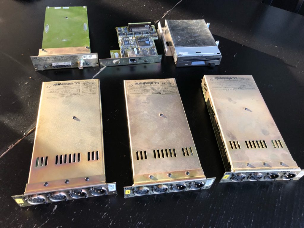
I recently purchased a « non working » TC Electronic System 6000, here’s a few notes of what I found while trying to fix it.
The TC Electronic System 6000 is based on two units:
The Mainframe with a floppy disk drive and a PCMCIA slot
The Remote + Icon
In my case, the remote unit works fine: the system boots properly, shows the Windows NT4 splashscreen and then the M6000 GUI.
The Mainframe unit is another story: the front panel is fixed red and.. stays red.
During a normal boot process, it’s supposed to access the floppy disk drive and the LED turns green once the boot is complete.
The Mainframe parts
The mainframe unit contains the following parts:
A power supply
A floppy disk drive
The AES/DSP cartridge
The AD/DA cartridge(s)
A network card
The mainboard
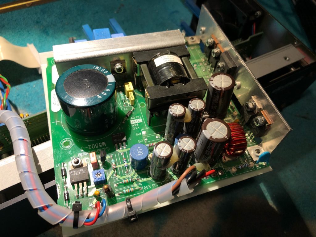
Power supply
The power supply unit delivers +/-5V and +/-20V:
Black / Red 5V
Black / Gray -5,2V
Black / Brown 20,5V
Black / Blue -21V
There’s also two wires connected to the fan (and a temperature probe): red/blue 5V. The potentiometer is probably used to adjust the temperature level triggering the fan.
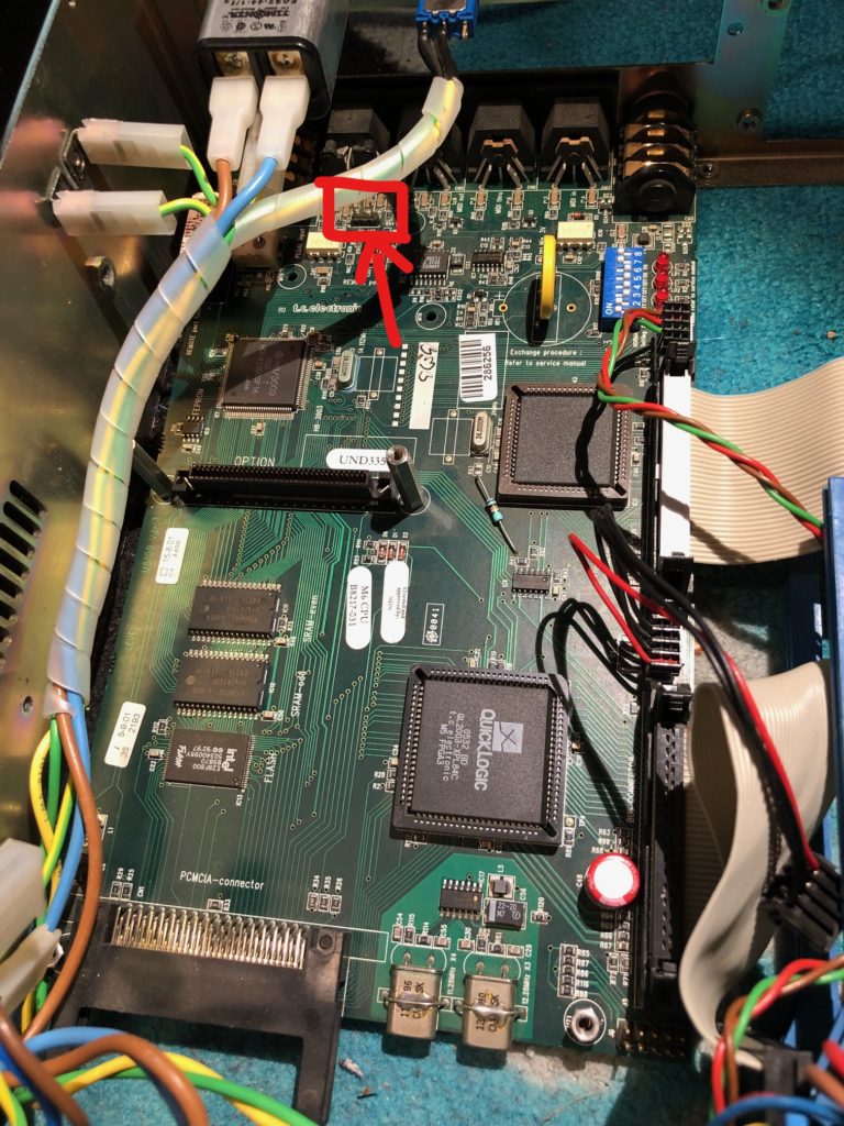
Motherboard
Taking a look inside the unit shows the following:
the internal DIP switches are in default position: ON ON OFF OFF OFF OFF ON ON
the LEDs are in the following state: ON OFF OFF BLINK
I tried booting without additional units (AD/DA, DSP, floppy disk drive, ethernet card) without success.
I also tried replacing the floppy disk drive with a Gotek floppy to USB emulator. This actually didn’t worked, the floppy drive is still not accessed. Since the Gotek drive has many configuration options it’s hard to tell if it’s normal.
The motherboard hosts:/
H8/3003, 16bits microcontroller
A QuickLogic FPGA
A floppy disk drive controller
Two RAM chips
A Flash chip
As far as I understand the system, the H8 is in charge of the boot process: read from the floppy disk drive (through the floppy disk drive controller) firmware updates. If found, flash the H8 bootloader itself (on the Flash chip) or the FPGA.
The bootloader firmware « M6bv20.ins » seems to contain debug strings, so there’s may be some serial output for debugging purpose.
The schematics shows that the H8 has two serial ports, and following these brings us to the DIN 7 « Remote port » at the back of the unit. The Serial port 1 (Tx0/Tx0) is connected as follow:
pin 2 : GND
pin 3: Tx
pin 4: Rx+
pin 5: Rx-
Moreover, the unused JP3 connector also exhibits the same serial port and really looks like a debug interface:
pin 1 (closest to the board corner): GND
pin 2 : Rx
pin 3: Tx
I used an USB to serial adapter to connect to this port, hoping for a terminal connection (or at least debug strings). Sadly, the port seems to be inactive, at least at this part of the boot process.
Reverse & DIP switches
The motherboard schematics provides interesting information on the DIP switches usage:
DIP #
ON
OFF
1 (sw1A)
Send boot_cs to inernal flash cs (Chip Select)
2 (sw1B)
Send pcmcia_mem_cs to fpga pcm_bus_cs
3 (sw1C)
Send boot_cs to fpga pcm_bus_cs
4 (sw1D)
Send pcmcia_mem_cs to flash cs
5 (sw1E)
Connect H8 MD2 to GND
Put 5V on the H8 MD2
6 (sw1F)
Put 5V on the H8 MD0/MD1
Connect H8 MD0/MD1 to GND
7 (sw1G)
Connect sram_cs to RAM chips CS
Disable external RAM
8 (sw1H)
Connect flash_cs to FLASH
Disable Flash
According the the schematic labels we also learn:
Set switches 1 and 2 to ON for ROM boot
Set switches 3 and 4 to ON for « CARD » boot (pcmcia sram)
Set switches 5 and 6 to ON for 8bits operation (16 bits otherwise)
ROM boot: (1&2)
The switches 1 and 2 are ON by default, which makes sense: the unit is supposed to boot on the ROM. When switch 1 is set to ON, the boot_cs (a signal used to enable/disable a chip, thus select who’s going to read data sent on a bus) is connected to the flash memory cs. The switch 2 connects the pcmcia_mem_cs (again, a signal used to enable access to the PCMCIA) to the FPGA. I guess the FPGA is in charge of driving the PCMCIA.
During boot: read flash memory
After boot, when using PCMCIA: use pcmcia
CARD boot: (3&4)
When set to ON, the 3 and 4 switches enable the CARD boot. Thanks to the 3rd switch, boot_cs signal is sent to the FPGA pcm_bus_cs, which probably propagates this to the PCMCIA slot. During boot, the PCMCIA card is then enabled. The switch 4, connects the pcmcia_mem_cs to the external flash cs, thus when accessing the PCMCIA slot after the boot process, the unit will actually read the external flash.
During boot: read pcmcia
After boot, when using PCMCIA: use external flash
Here I learned something protentially fixing my issue: I suspect the bootloader to be corrupted and thus not accessing the floppy disk drive. If if use CARD boot mode, with a pcmcia sram memory card contaning the boot image (« M6bv20.ins ») raw written on it, I may actually bypass the flash memory issue. I found some technical documentation explaining that the M6bv20.ins should be copied to a floppy disk, then flashed on the SRAM pcmcia using a M5000 unit (« Wizard to disk » tool).
8/16 bits (5&6):
Switches 5 and 6 interacts with the H8/3003 MD0, MD1 and MD3 pins.
Mode 3: Address pins A23 to A0 are enabled, permitting access to a maximum 16-Mbyte address space. The initial bus mode after a reset is 8 bits, with 8-bit access to all areas. If at least one area is designated for 16-bit access in ABWCR, the bus mode switches to 16 bits.
Mode 4: Address pins A23 to A0 are enabled, permitting access to a maximum 16-Mbyte address space. The initial bus mode after a reset is 16 bits, with 16-bit access to all areas. If all areas are designated for 8-bit access in ABWCR, the bus mode switches to 8 bits.
So clearly, these two switches are used to select 8 or 16bits memory addressing, keeping the default position to 16bits (off/off) is a good option since I do not plan to rewrite the whole firmware 🙂
External RAM (7)
When OFF, switch 7 disables the two external RAM chips, thus the H8 CPU can only use its internal memory. Clearly we don’t want this and we’ll let this switch to ON.
External Flash (8)
When OFF, switch OFF disables the Flash chip during flash operations. Again, we don’t want this and we’ll let this switch to ON.
Reverse & JTAG
The J6 connector is a JTAG debug interface, connected to the FPGA. It’s probably used to load the fpga firmware in the factory. Since I don’t have a JTAG probe (and passing sniffing is pointless), it’s currently useless.
Factory setup
As far as I currently understand the motherboard, I suppose that:
the H8 firmware is loaded using the DIP Switch 3&4 and a PCMCIA card with the bootloader firmware written. Thus, the H8 boots properly and is then able to « update » the bootloader using the floppy disk, writing the program on the flash.
the FPGA firmware is loaded using the JTAG interface, probably prior to the H8, since the FPGA seems to be in charge of controlling the floppy disk driver.
Host Bus interface
I used my Salaea probe to watch traffic from the motherboard to the Host Bus Interface card. I didn’t tried to decode the whole traffic, but clearly there’s some.
Flash memory bus
I’m currently trying to scan the accesses to the flash memory bus, hoping it may help me to find what’s going on. The best place to sniff the bus seems to be the Ethernet card: the card shares the BUS with the flash chip, and the connector can easily be used to connect my probes. I’ll have to collect 3 bits lanes for each run and then reassemble, my Salaea is the 4 channel version. 1 channel will be used for the Clock (pin 43) and the 3 others for data.
So your keyboard has a Pitch Wheel but not an aftertouch one? Worse, keyboard still uses channel 7 (and you’ve lost the manual) and you want Aftertouch events to be sent on channel 1.
It’s pretty easy so setup a simple configuration to convert Pitch Wheel messages into Aftertouch.
The header section of the figuration file is again qui simple, just set the input MIDI interface and the output one.
We can achieve our use case with just one simple rule.
Filter:
On the filter section, we set MsgType to « Pitch Wheel » in order to look for these messages on our input interface.
We use ‘7’ for midi channel because your Pitch Wheel events are sent on this channel (and you’ve lost the manual, remember).
We set the Pitch value to ‘*’ because we want to process all values.
Transform:
Again we won’t use the Transform section here, we want to map the complete pitch range (0 to 127) to aftertouch events (0 to 127), so we set it to « None ».
Generator:
We want to send Aftertouch events, so we set MsgType to « Aftertouch ».
We want to re-emit the message on the channel 1 instead of the original 7 channel: we set the Channel to ‘1’.
Now comes the (almost)-tricky part:
Pitch Wheel have Pitch values
Aftertouch have Pressure values
We want to copy the pitch value read from the Pitch Wheel event to the pressure value of the Aftertouch event. We canot use « * » as a Pressure value because Pitch Wheel and Aftertouch are distinct events.
On a Generator configuration, values can be set to:
A given hardcoded value (what we did for the MIDI Channel)
‘*’: The original value of same type (what we did on our previous example with Note on events)
‘$’: The extracted value from the captured message
What value is extracted from the Pitch Wheel message? The Pitch value!
So by using « Pressure »: « $ » we just copy the extracted Pitch value to the Pressure value.
By using a similar technique, you could also use the Pitch Wheel to generate NoteOn events, use Notes to generate Program Change events and so on!
Let’s start with a very simple use case: « I want to forward all messages received on my input MIDI interface to my output MIDI interface ».
This may typically happen when you have a MIDI Usb keyboard connected to your audio interface and you want to send everything to you freshly acquired analog synthesizer connected to your MIDI output.
Our configuration file will first specify your MIDI input and output devices.
Simply run MIDIRouter with no arguments to list available devices:
Usage: ./midirouter <config file>
MIDI inputs:
   Périphérique MIDI USB
   Korg
   MOOG
   Faderfox EC4
   Port 1
   Port 2
   Port 3
   Port 4
   Port 5
   Port 6
   Port 7
   Port 8
MIDI outputs:
   Périphérique MIDI USB
   Korg
   MOOG
   Faderfox EC4
   Port 1
   Port 2
   Port 3
   Port 4
   Port 5
   Port 6
   Port 7
   Port 8
Let’s say I want to route everything from « Korg » to « MOOG ».
The « DefaultPassthrough » simply tells the MIDIRouter to forward all messages not matching any other rule. Since we don’t have any other rule set, this default behaviour will match all captured messages on the input interface.
The « Verbose » option is useful when setting everything up: it will show a message everytime a MIDI event is received (you can switch it to ‘false’ once everything works fine).
Note On/off forward only
On our previous example we’ve used the DefaultPassthrough feature to allow a complete forward of all messages from the input MIDI device to the output MIDI device.
Now we may not want to send everything to our vintage Analog Synth since it only supports NoteOn and NoteOff MIDI mesages. In order to do that, we will use what is the main feature of MIDIRouter: « rules ».
A « Rule » is built using three main sections:
A filter which describes what kind of MIDI message to look for on the input MIDI interface
A transformation which optionally defines how you want to change the extracted value
A generator which describes what kind of MIDI message to replay on the output MIDI interface
Our complete forward scenario is quite simple:
Filter: we want to match any Note On or Note Off message whatever the MIDI channel, value or velocity
Transform: we don’t want to transform anything
Generator: we want to replay using the same type of MIDI message (Note on, note Off), same MIDI channel, same note, same Velocity
We will here need two rules, one for the Note On events and one for the Note Off events.
Let’s start with Note On forward.
{
    "SourceDevice": "Korg",
    "DestinationDevice": "MOOG",
    "DefaultPassthrough": false,
    "Verbose": true,
    "Rules": [
        {
            "Name": "Raw forward of any Note On",
            "Filter": {
                "Name": "Note On in (I can write anything here)",
                "MsgType": "Note On",
                "Channel": "*",
                "Settings": {
                    "Note": "*",
                    "Velocity": "*"
                }
            },
            "Transform": {
                "Mode": "None"
            },
            "Generator": {
                "Name": "Note On out",
                "MsgType":"Note On",
                "Channel": "*",
                "Settings": {
                    "Note": "*",
                    "Velocity": "*"
                }
            }
        }
    ]
}
In the first part of this configuration file, we have the same section defining the input and output. Note that we’ve disabled the Defaultpassthrough option.
Then we have the « Rules » array which – for now – only contains one rule for our « Note On » events. The « Name » fields can be used to put any comments to be used for display only.
The « Filter » is built using:
MsgType: the type of midi message to look for (among « Note On », « Note Off », « Aftertouch », « Control Change », « Program Change », « Channel Pressure », « Pitch Wheel »). Here we set it to « Note On »
Channel: the MIDI channel to look for (1 to 16). Here we want to match any channel and use ‘*’.
Now comes the « Note On » specific settings which are « Note » (the note value) and « Velocity ». Since we want to match any note or velocity, we use ‘*’ again.
Then comes the « Transform » entry which would technically allow us to transform a note to another one. Here we just want to replay the MIDI message as it, so we use « None ».
The « Generator » section describes what kind of MIDI message we want to generate when a MIDI message matching our filter is captured. These settings are quite similar to the filter settings.
MsgType: the type of midi message to generate (among « Note On », « Note Off », « Aftertouch », « Control Change », « Program Change », « Channel Pressure », « Pitch Wheel »). So here we set it to « Note On »
Channel: the MIDI channel to set (1 to 16). Here we want reuse the same MIDI channel found on the captured Note on, we set it to « * ».
Now comes the « Note On » specific settings which are « Note » (the note value) and « Velocity ». Since we want to replay the same note and velocity, we use ‘*’ again.
And that’s it: the rule will match all Note on events and replay them to the output interface using the exact same settings (MIDI channel, note, velocity).
Because we want to send also Note Off messages, we add another rule with very similar settings:
On the next article, we will see how we can send Pitch Wheel events captured on a given MIDI channel to another MIDI channel and transform them to Aftertouch events:
I’ve developped a tool for MacOS called « MIDIRouter » which does what the name implies: it’s able to route (and transform) MIDI messages over MIDI interfaces.
Before going deeper into its features, let’s try to understand what I’m trying to achieve.
I have a few multi-effects on my studio (an Ensoniq DP/4, a Digitech Studio Quad v2) and actually I don’t use them that much. They’re behind me on a rack which is not really convenient to update settings and listen to the results, especially for reverbs.
Using the EC4, I’m able to associate any VPot to a given MIDI mesage type: send a program change, a control change (pitch bend, aftertouch, Note On, etc.) and customize displayed text to my needs.
This looked quite promizing, but the EC4 has some limitations:
When using a ControlChange, displayed value does not necessarily match with the ouput value. Control Changes values can be 7 bits (0 to 127) or 14 bits (0 to 16383) while I can setup displayed value to (0, 127), (0,1000), etc.
The Ensoniq DP/4 requires proprietary Sysex messages to change its parameters, this is not supported by the EC4
I plan to use the EC4 for other purposes (control DAW plugins is among them), so I want it to be connected to my Mac and forward some messages to my effects chain
So I needed a software that would be able to:
Watch an input MIDI device for a certain type of messages (with wildcard support)
Extract a value (7bits or 14bits) from those messages (a program value from a Program Change, a control value from a Control Change, etc.
Remap the value to the expected output value range (« my EC4 shows a value in the range [0-100], sends a [0-127] value and I want to then to my effect a [0-64] value »)
Re-emit a MIDI message to the output interface using eventually another MIDI message type (« transform the EC4 Control Change messages into DP/4 Sysex messages) including the extracted value
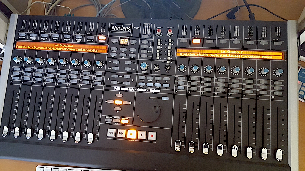
Just a few technical notes on debugging the SSL Nucleus (mk1) through serial port. I will enventually update this article with additional commands tests.
Playing with the LCD driver
First of all, you’ll need a USB to serial cable, which can easily be found on amazon, aliexpress and so on. Such a cable it about 1€, don’t spend more on it!
On macOS: open a Terminal and type:
screen /dev/tty.wchusbserial141330
The actual name of the device may differ, but it’s probably be something close.
You now have a pretty nice shell, opened on your Nucleus, type « help » to show all available commands:
CMD>help

TP220_3 [] Daw channels layer 3 diags
ALLOC_3 [] DAW allocator
TP220_2 [] Daw channels layer 2 diags
ALLOC_2 [] DAW allocator
ACTIVE  [] Ptoosl active send
TP220_1 [] Daw channels layer 1 diags
ALLOC_1 [] DAW allocator
TP180   [] Soft key diag
TP186   [] Layer Control
TP215   [] control groups
TP177   [] UDP midi
IP      [] TCPIP Diags
ETHer   [] PX1 Ether diags
DAW     [] DAW config
CCC     [] cc config
SOKS    [] Soft key diag
FLIST   [] function lists
TP234   [] Centre meters
TP199   [] USB KBD Functions
SVEN2   [] 7 seg diag
SURF    [] ctrl surface diags
TP5     [] Control manager
TP86    [] Power up restore
LOG     [] Logging
FRAM    [] FRAM cmds
FS      [] File system
RTC     [] Real time clock
USB     [] USB Kbd Diags
TH6     [] SPI Access
TH17    [] 675 Live Bus
TH16    [] MD Bus
REP     [] Diags
TH18_0  [] LCD Driver
TH19    [] Firmware Revision
INTEG      check code integrity
CRASH      crash system
VER        SW version
G          Flip back to the trusty "G" interpreter; same as <ctrl D>
DEBUG   [] Stuff which should probably be somewhere else
HEAP    [] Heap diags
MOS     [] Operating system diagnostics
FILES      Show file task ids
REPort  [] Diagnostic reporting

CMD>
Now, it’s probably the best time for the traditional disclaimer: you may break things here, I’m not responsable for anything.
Command
Short description
Description
TP220_3
Daw channels layer 3 diags
untested
ALLOC_3
DAW allocator
untested
TP220_2
Daw channels layer 2 diags
untested
ALLOC_2
DAW allocator
untested
ACTIVE
Ptoosl active send
untested
TP220_1
Daw channelslayer 1 diags
untested
ALLOC_1
DAW allocator
untested
TP180
Soft key diag
untested
TP186
Layer Control
untested
TP215
Control Groups
List all internal states for all DAW sync-ed items (faders, buttons, pots, etc.).
TP177
UDP midi
untested
IP
TCPIP Diags
untested
ETHer
PX1 Ether Diags
untested
DAW
DAW Config
untested
CCC
CC config
untested
SOKS
Soft key diag
untested
FLIST
function lists
untested
TP234
centre meters
Setup the MIC meter (from 1 to 2) led display to a given value (from 0 4000) to . Ex: « TESTmtr 1 2000 » lights up half the left channel leds.
TP199
USB KBD functions
untested
SVEN2
7 seg diag
Shows a 2 letter text on the center « MODE » 7 segments display.
SURF
ctrl surface diags
untested
TP5
Control manager
untested
TP86
Power up restore
untested
LOG
Logging
Dumps the last boot message (see below)
FRAM
FRAM cmds
untested
FS
File system
untested
RTC
Real Time Clock
untested
USB
USB kbd diags
untested
TH6
SPI Access
untested
TH17
675 Live Bus
untested
TH16
MD Bus
untested
REP
Diags
untested
TH18_0
LCD Drivers
A set of commands to display text on the left/right two lines LCD
TH19
Firmware revision
Shows the firmware revision « FPGA Firmware version is : V2.01 »
INTEG
check code integrity
Check the OS integity, supposed to show « Code integrity test passed. »
CRASH
crash system
untested
VER
SW version
Shows the software version: « Software : Nucleus Version : V1.6/2 I Build : Tue 17 Jun 14, 15:59:17 by alanj »
G
Flip back to the trusty « G » interpreter; same as
untested
DEBUG
Stuff which should probably be somewhere else
untested
HELP
Heap diags
untested
MOS
Operating system diagnostics
untested
FILES
Show file task ids
untested
REPort
Diagnostic reporting
untested
List of commands
Boot logs:
Version        : V1.6/2 I
Build          : Tue 17 Jun 14, 15:59:17 by alanj
TP96: Monitor type is SSL Aude 505 CPU Monitor


TH19: Firmware: V2.01
th5_control_bus
th16_bud_md_bus
th5_control_bus
th17_bud_live_bus
TF1: File system
th12: MMC/SD init: Caching ON
th12: card type 8
TF1: File system status: OK
TF1: 3896246272/3942645760 bytes free
tp301: Read 8192 bytes of FRAM data from disk (requested 8192)
TS4: Crash logger
tp86: Valid console PUR data found
TP5: Control manager
tp299: xdaw control surface
tp234_bud_centre_meters
TP226: Function lists
TP184: Soft Key Manager
TP253: CC Config
TP190: DAW config
tp190: setting profile 'BG Protools' ('/userprof/4') on daw layer 1
tp190: setting profile 'B Logic Standard' ('/userprof/2') on daw layer 2
tp190: setting profile 'Live Standard' ('/sslprof/14') on daw layer 3
PX1: Ethernet
PX1: mem map B
PX1: 82559 Detected
TC4: TCPIP setup
TC4: 31 bytes of FRAM used
TC4: Using DHCP assigned addresses
TC1: OpenTCP Init
TC1: Using DHCP assigned addresses
TC1: MAC address is 58:0c:13:04:02:90
TP185: Soft Key Assignments
TP219: Layer 1 initialisation for protocol 'HUI'
TP212 Creating HUI layer. First chan 1, last chan 16
tp75: constructing HUI LUT
TP219: Layer 2 initialisation for protocol 'Logic Audio'
TP213 Creating MCU layer. First chan 1, last chan 16
tp75: constructing MCU LUT
TP160: Starting 2 MCU handhake ports for layer 2
tp160: rcvd port active on port 0
tp160: rcvd port active on port 1
TP219: Layer 3 initialisation for protocol 'Logic Audio'
TP213 Creating MCU layer. First chan 1, last chan 16
tp75: constructing MCU LUT
TP160: Starting 2 MCU handhake ports for layer 3
tp160: rcvd port active on port 0
tp160: rcvd port active on port 1
TP176: AWS90 Remote [serial no. 262800]
TC1: Starting IP services
TC1: got DHCP IP address 10.0.1.107
TP277: Calibrating fader touch 1...16
TP277: Calibrating faders 1...16

Software       : Nucleus
Version        : V1.6/2 I
Build          : Tue 17 Jun 14, 15:59:17 by alanj

Code integrity test passed.
Boot completed in 1030 ticks.