
The Fairchild 661
The Fairchild 661 is an optical gate which has nothing to do with the very famous Fairchild 660.
The 661 a quite simple unit:
- The input signal goes through a teansformer then a transistor based circuit
- The result is used to light a bulb
- The signal to be « gated » goes through a « Light Dependant Resistor » (LDR). When the light bulb is bright (ie. a loud level), the resistor value descreases, thus the signal is not attenuated.
The 661 includes a Threshold and a Release knobs.
So what about the Fairchild 663?
The Fairchild 663 compressor, uses basically the same circuit but this time the LDR is connected from the signal to the ground. Thus, when the light is bright (ie. a loud level), the resistor value decreases and more signal goes to the ground.
Let’s look at the circuits!
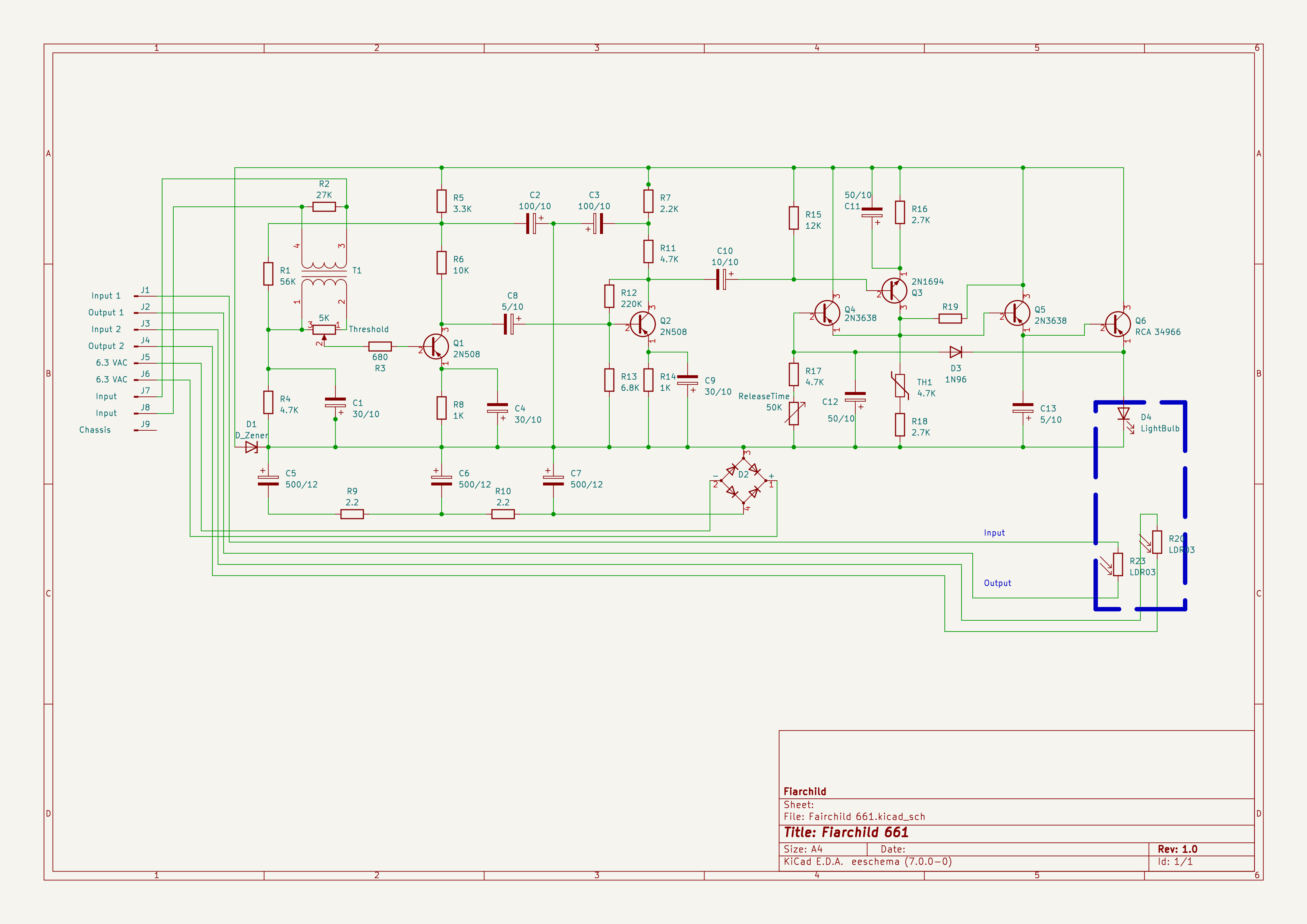
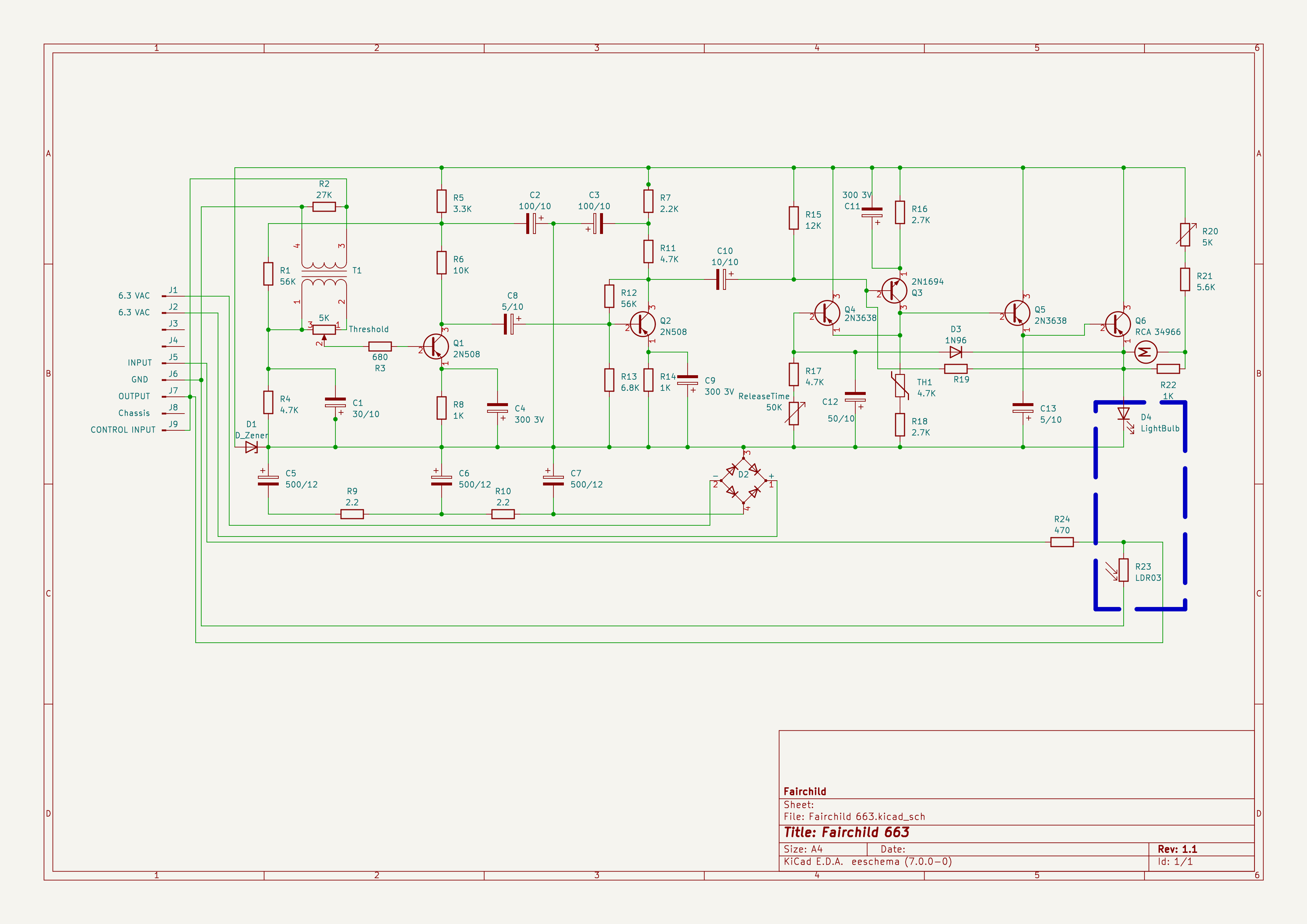
If we compare these two schematics, we can see that:
- R19 is wired differently
- the two LDRs are wired differently
Converting to DC
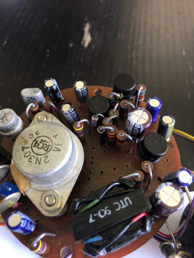
The diode rectifier (D2), C5, C6, C7, R9, R10 and D1 are used to convert the 6,3V AC power supply to (almost) DC.
Since we plan to power up the Fairchild using 9V DC (much more convenient that the original 6.3V AC), we will need to get rid of the useless components:
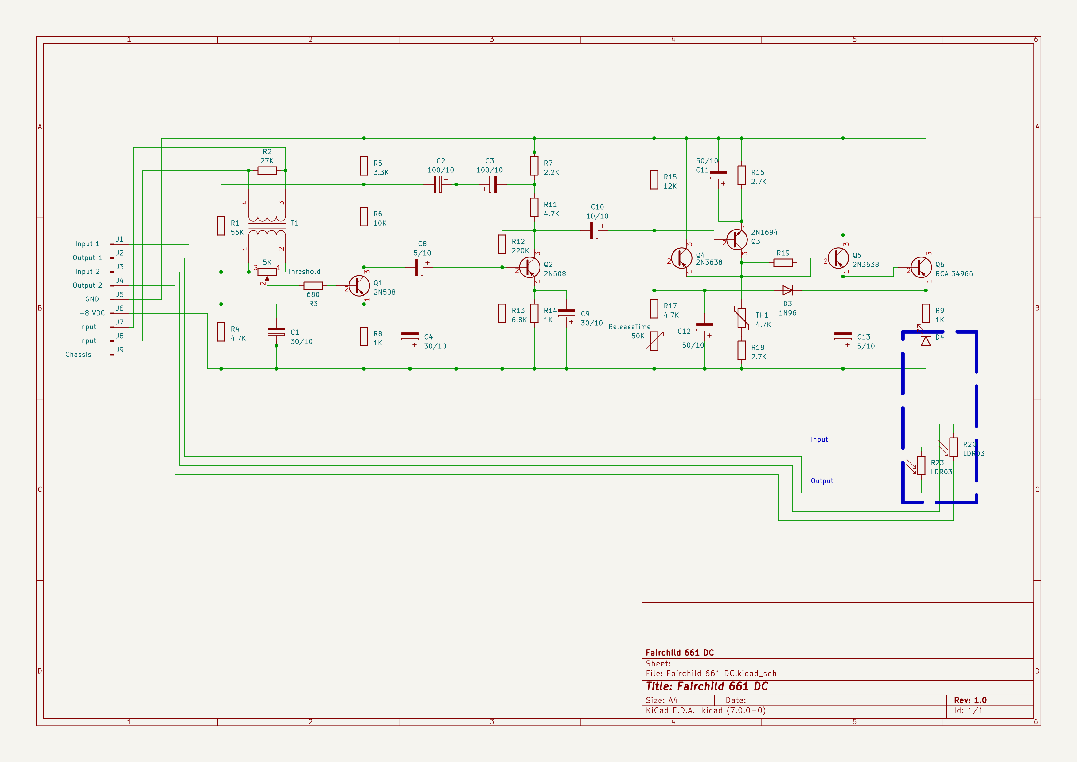
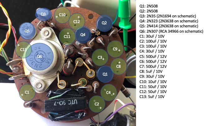
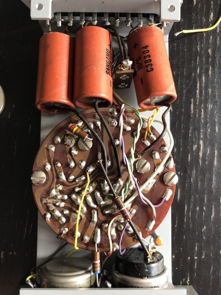
Step 1: Remove the 3 large orange capacitors
Step 2: remove the 4 diodes (D2), R9 and R10:
What about D1? Well is seems that this component was actually not present of most 661 boards.. Let’s ignore it!
Step 3: Setup the power wires
The Original 6.3V comes from the white and green wire pair.
Unsolder those two wires.
Solder the green one (which will be our +9V) and the white one (GND) as follow:
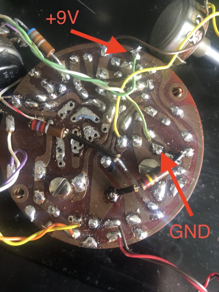
And that’s it, you can now power your 661 or 663 using 9V DC!
Converting the 661 to a 663
Part 1 : rewiring the LDR
I won’t go into much details about rewiring the LDRs: on the 661 these were simply placed on the signal hot pin. On a compressor, we want the opposite behaviour:
- the input XLR is connected to the output XLR, as it
- the two LDR wires (red/black or orange/yellow) must be connected from the XLR hot pin to the XLR ground
Part 2: moving R19
R19 is on the backside of the PCB (solder side), remove it:
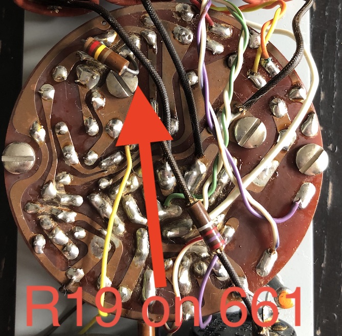
Now re-solder it as follow:
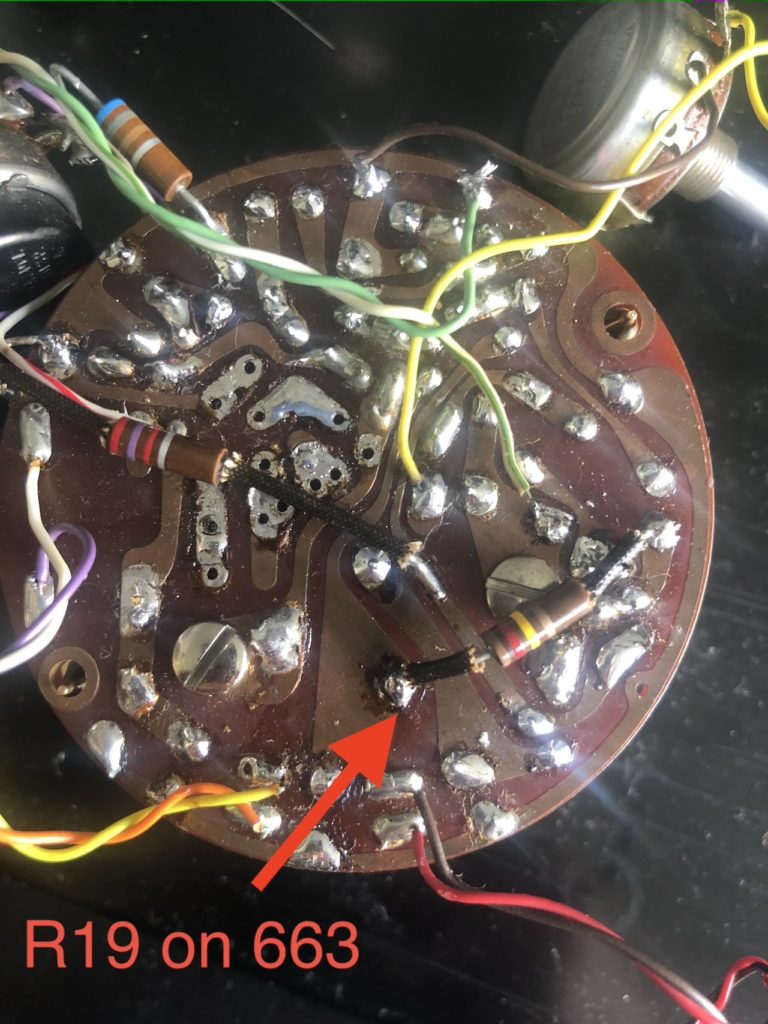
And that’s it, your 661 gate is now a 663 compressor!
General purpose updates
In order to get a fully functional 663 (or 661), you may also perform the following:
- replace all caps with same (or close) values. Since no audio actually goes through the circuit you won’t need super audio grade capacitors.
- the original LDRs are probably dead, you may want to replace them otherwise the compressor effect wil be really subtle https://www.aliexpress.com/item/1005002578300247.html
- the original light bulb is eventually dead, I’ve tried different options and ended up with these cheap bulbs: https://www.aliexpress.com/item/1005004900146314.html? 3mm / 6V